
A manual transfer switch is a crucial component in backup power systems, enabling safe transitions between utility and generator power. Wiring diagrams ensure reliable, efficient connections.
1.1 What is a Manual Transfer Switch?
A manual transfer switch is an essential electrical device designed to manually transition power from a primary source to a secondary source, such as a backup generator. It ensures a safe and reliable power supply during outages, preventing disruptions in critical systems. Typically installed alongside the main electrical panel, this switch allows for smooth operation without the need for automatic controls. Its primary role is to prevent backfeeding, which can damage equipment or pose safety risks. The switch is widely used in both residential and commercial settings, offering a straightforward solution for maintaining electrical safety and continuity. The wiring diagram for a manual transfer switch provides a clear guide for connecting it to the generator and main panel, ensuring correct wire connections and safe operations.
1.2 Importance of a Manual Transfer Switch in Electrical Systems
A manual transfer switch is vital for ensuring electrical safety and reliability in systems with backup power sources. Its primary role is to prevent backfeeding, which can cause electrical fires or damage to utility equipment. By isolating the main power source from the generator, it protects both the electrical grid and connected devices. Additionally, it provides a clear point of disconnection, simplifying maintenance and troubleshooting. In residential settings, it safeguards critical appliances during outages, while in commercial environments, it ensures uninterrupted operations. The switch also reduces the risk of power surges and voltage fluctuations, making it an indispensable component for systems requiring consistent and secure power delivery. Proper installation, guided by a wiring diagram, ensures these benefits are realized effectively and safely.

Components of a Manual Transfer Switch
A manual transfer switch consists of a main switch mechanism, input/output terminals, indicator lights, and circuit breakers or fuses to ensure safe and reliable power transfer.
2.1 Main Switch Mechanism
The main switch mechanism is the core component of a manual transfer switch, enabling manual switching between utility and generator power; It ensures safe disconnection from the grid, preventing backfeeding. Constructed from durable materials like metal, the mechanism provides reliable operation under various electrical conditions. Its design allows for smooth transitions, minimizing power interruptions. Proper installation and alignment are critical to ensure the switch functions as intended. The mechanism is typically rated for specific voltages and currents, matching the electrical system’s requirements. Regular maintenance, such as cleaning contacts, ensures optimal performance. Understanding its operation is essential for safe and efficient power management during outages.
2.2 Input and Output Terminals
The input and output terminals on a manual transfer switch are essential for connecting power sources and loads. The input terminals are designed to receive power from the main electrical grid and the backup generator. These terminals are clearly labeled to ensure proper connections, with distinct sections for utility and generator inputs. The output terminals distribute power to critical circuits in the home or business, such as lighting, heating, and appliances. Proper sizing of wires for these terminals is crucial to handle the electrical load safely. Color coding and clear labeling of wires simplify installation and maintenance. Ensuring tight, secure connections at these terminals prevents arcing and overheating, which could lead to system failures or safety hazards. Regular inspection of these terminals is recommended to maintain reliability and performance. Proper installation ensures seamless power transfer during outages.
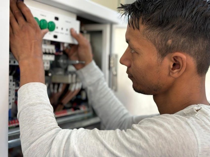
2.3 Indicator Lights and Status Indicators
Indicator lights and status indicators on a manual transfer switch provide critical visual feedback about the system’s operational state. These indicators, often LED lights, show whether the switch is connected to the utility grid or the generator. They may also display fault conditions, such as overload or phase imbalance. The lights are typically color-coded, with green indicating normal operation on the grid, red for generator mode, and yellow or amber for fault states. Some switches include additional indicators for circuit activity or voltage levels. These features enhance monitoring and troubleshooting, ensuring safe and efficient power management. Proper wiring of these indicators is essential, as they rely on internal circuits to function accurately. They are invaluable for maintaining system reliability and user awareness during power transitions. Regular checks ensure they operate correctly.
2.4 Circuit Breakers and Fuses
Circuit breakers and fuses are essential components in a manual transfer switch system, providing overload and short-circuit protection. These devices are integrated into the switch to safeguard the electrical system from damage. Circuit breakers can be reset after tripping, while fuses must be replaced when they blow. Proper sizing and rating of these components are critical to ensure they protect both the main power source and the generator. They are typically installed on the input and output terminals of the transfer switch, preventing excessive current from flowing through the system. This protection is vital for maintaining the integrity of the electrical connections and ensuring safe, reliable operation. Regular inspection of circuit breakers and fuses is recommended to verify their functionality and prevent potential hazards. Their role in protecting the system cannot be overstated.

Understanding the Wiring Diagram
A wiring diagram provides a visual guide for connecting components in a manual transfer switch system, ensuring correct installation and safe, efficient power transfer between sources.
3.1 Overview of the Wiring Diagram
The wiring diagram outlines the electrical connections for a manual transfer switch, detailing how to link the main power source, generator, and load center. It simplifies the installation process by providing a clear, step-by-step visual guide. The diagram typically includes symbols for switches, circuit breakers, and connectors, ensuring that each component is correctly connected. By following the diagram, users can ensure safe and efficient power transfer, avoiding potential hazards like backfeeding. The overview also highlights the importance of proper wire sizing and connections to maintain system performance and reliability.
3.2 Symbols and Notations Used in the Diagram
The wiring diagram uses standardized symbols to represent components such as switches, circuit breakers, and connectors. Common symbols include circles for switches, rectangular boxes for circuit breakers, and lines representing wires. Color coding is also used, with black wires typically indicating hot connections, white for neutral, and copper for ground. These notations ensure clarity and consistency, making it easier to interpret the diagram. Arrows may indicate the flow of electricity, while dashed lines could denote optional connections. Understanding these symbols is crucial for accurate installation and troubleshooting, ensuring the manual transfer switch operates safely and efficiently.
3.3 Color Coding of Wires
In the wiring diagram for a manual transfer switch, wires are color-coded to ensure clear identification and safe connections. Black wires typically represent “hot” or live wires, carrying electrical current from the power source. White wires signify neutral connections, completing the circuit. Copper wires are reserved for grounding, providing a safe path for excess current. This standardized coloring helps technicians and homeowners quickly identify each wire’s function, reducing the risk of errors. Proper color coding is essential for maintaining safety, preventing short circuits, and ensuring compliance with electrical standards. Consistent use of color coding across the diagram simplifies the installation and troubleshooting process, making it easier to understand and work with the manual transfer switch system effectively.
Installation Process
Installing a manual transfer switch involves preparing the site, connecting input and output wires, and testing the system. Follow the wiring diagram for safe, accurate connections.
4.1 Preparing the Site for Installation
Preparing the site for manual transfer switch installation involves ensuring compatibility with your generator and electrical system. Refer to the switch’s nameplate to verify voltage, current, and power ratings match your setup. Ensure the area is clean, dry, and free from obstructions. Shut off the main power supply before starting work. Use personal protective equipment (PPE) for safety. Review the wiring diagram to understand connections and plan the layout. Remove insulation from wires as specified, typically 5/8-inch from the black wire, and organize them for neat installation. Verify all components, such as circuit breakers and terminals, are in good condition. Proper site preparation ensures a smooth and safe installation process.
4.2 Connecting the Input Wires
Connecting the input wires to the manual transfer switch requires careful attention to the wiring diagram. Begin by identifying the main power line and generator input terminals on the switch. Use yellow wire connectors to secure the black wire from the transfer switch to the load center, ensuring a tight twist for reliability. Refer to the diagram to match the correct wires from the utility and generator sources to their respective terminals. Double-check all connections for compatibility and proper alignment. Avoid loose wires, as they can lead to unsafe conditions. Once connected, verify that the wires are neatly organized and secured to prevent damage. Always follow safety guidelines, such as wearing PPE, to ensure a safe and efficient installation process.
4.3 Connecting the Output Wires
After connecting the input wires, focus on the output wires, which supply power to the selected circuits. Refer to the wiring diagram to identify the output terminals on the manual transfer switch, typically labeled for specific loads. Use the correct wire connectors to secure the wires to the load center, ensuring compatibility with the switch’s rating. Designate critical circuits, such as the refrigerator or furnace, to specific switches for easy control. Tighten all connections firmly to avoid loose wires, which can cause electrical issues. Once all output wires are connected, organize them neatly to prevent tangling or damage. Double-check the wiring diagram to confirm that all circuits are properly assigned and functioning as intended. This step ensures reliable power distribution during a generator takeover.
4.4 Testing the Connections
After completing the wiring, thoroughly test the connections to ensure proper functionality. Start by turning off the main power and generator, then use a multimeter or circuit tester to verify voltage and continuity across all connections. Check for any short circuits or open circuits, ensuring the wiring matches the diagram. Simulate a power outage by switching to the generator, observing if the transfer switch activates correctly. Monitor the indicator lights to confirm the power source transition. Test each circuit individually to ensure they receive power from the generator. Address any issues immediately, such as incorrect voltage readings or malfunctioning indicators. This step ensures the system operates safely and reliably, preventing potential hazards like backfeeding or power loss. Refer to the wiring diagram for specific testing procedures and consult a professional if uncertainties arise.

Safety Considerations
Always follow safety guidelines to prevent electrical hazards. Ensure proper wiring to avoid backfeeding and use a multimeter to verify connections before activating the switch.
5.1 Electrical Safety Precautions
When working with a manual transfer switch, always disconnect power sources to prevent electrical shocks. Ensure the generator is properly grounded and use insulated tools. Verify all connections are secure and free from damage. Never touch live wires or components without proper protection. Always follow local electrical codes and manufacturer guidelines. If unsure, consult a licensed electrician to avoid potential hazards. Proper safety measures ensure reliable operation and protect people and equipment from harm. Regular inspections and testing are essential to maintain system integrity and safety.
5.2 Preventing Backfeeding
Preventing backfeeding is crucial to ensure safety and avoid damage to electrical systems. A manual transfer switch acts as a physical barrier, disconnecting the house wiring from the grid when using a generator. Proper installation is key; the switch must be wired to prevent any direct connection between the generator and utility lines. Using a switch with a “break-before-make” mechanism ensures no overlap between power sources. Proper grounding of the generator to the house’s system is essential to prevent backfeeding. Testing the system under load with a multimeter can verify no voltage is present on utility lines during generator use. Regular maintenance, such as cleaning and inspecting the switch, ensures continued functionality. Following local codes and manufacturer guidelines is vital for effective backfeeding prevention.
5.3 Emergency Shutdown Procedures
Emergency shutdown procedures are critical for safely managing power transitions in manual transfer switch systems. In case of a power outage or system failure, disconnect the generator immediately to prevent damage. Switch off the main circuit breaker to isolate the electrical system. Ensure all connected devices are turned off before attempting any shutdown. If the system is in use, allow it to cool down to avoid thermal stress. Follow the manufacturer’s guidelines for sequencing shutdowns and startups. Always verify that no power is present using a multimeter before performing any maintenance. Regular drills can help ensure readiness in emergency situations. Proper adherence to these procedures minimizes risks and ensures system integrity during unexpected events.

Troubleshooting Common Issues
Troubleshooting common issues with manual transfer switches involves identifying faulty connections, tripped circuit breakers, or incorrect wiring. Use a multimeter to test circuits and consult wiring diagrams for solutions.
6.1 Identifying Common Problems
Common issues with manual transfer switches often stem from wiring errors, faulty connections, or tripped circuit breakers. Signs include power failure, flickering lights, or circuits not switching. Use a multimeter to test for voltage drops or short circuits. Consult the wiring diagram to verify connections and ensure all terminals are secure. Loose wires, incorrect wire sizing, or misconfigured circuits can disrupt operation. Additionally, backfeeding or improper generator synchronization may cause system malfunctions. Always refer to the wiring diagram to trace and resolve issues efficiently, ensuring safe and reliable power transfer. Regular inspections and testing can prevent many of these problems, maintaining optimal performance.
6.2 Diagnosing Wiring Issues
Diagnosing wiring issues in a manual transfer switch involves systematic checks to identify faults. Start by reviewing the wiring diagram to understand connections. Use a multimeter to test for voltage drops, short circuits, or open circuits. Check for loose or corroded connections, which can cause intermittent power issues. Inspect wires for damage or incorrect sizing, as this can lead to overheating or fire hazards. Verify that all terminals are securely fastened and properly labeled. Ensure the neutral and ground wires are correctly connected to prevent backfeeding. If a circuit breaker trips repeatedly, it may indicate an overload or short circuit. Always disconnect power before performing detailed inspections. A thorough diagnostic process ensures safe and reliable operation of the transfer switch, preventing potential electrical hazards and system failures. Regular testing and maintenance are essential for long-term functionality.
6;3 Tools and Equipment Needed for Troubleshooting
Troubleshooting a manual transfer switch requires specific tools to ensure safety and accuracy. Essential tools include a multimeter for voltage and circuit testing, wire strippers for repairing connections, and a circuit tester to identify live wires. A screwdriver set is necessary for accessing and adjusting components. Pliers and wrenches may be needed for tightening loose terminals. Safety equipment like insulated gloves and goggles should always be worn to prevent electrical shock. A wiring diagram is crucial for referencing connections and identifying potential issues. Additional tools such as a non-contact voltage tester and a thermal imaging camera can help detect hidden problems like overheating components. Having the right tools ensures efficient and safe troubleshooting, minimizing risks and downtime. Proper equipment is vital for diagnosing and resolving wiring issues effectively.
Best Practices for Wiring
Always use the correct wire size and ensure connections are tight and secure. Refer to the wiring diagram for guidance and follow manufacturer instructions for safe installation.
7.1 Selecting the Right Wire Size
Selecting the correct wire size is critical for safe and efficient electrical connections. The wire size must match the current rating of your manual transfer switch and the load it will handle. A wire that is too small can overheat, leading to potential fire hazards, while a wire that is too large may be unnecessary and costly. Refer to the wiring diagram provided with your manual transfer switch to determine the appropriate gauge for your specific application. Always ensure the wire size complies with local electrical codes and the manufacturer’s specifications. Proper wire sizing ensures reliable power transfer and maintains the integrity of your electrical system. By following these guidelines, you can avoid common issues and ensure a safe, efficient installation.
7.2 Ensuring Proper Connections
Ensuring proper connections is essential for the safe and reliable operation of a manual transfer switch. Always follow the wiring diagram provided with your switch to connect wires correctly. Use appropriate wire connectors or terminals to secure connections, and tighten all screws firmly. Avoid loose connections, as they can cause arcing or overheating. Double-check that all wires are connected to the correct terminals, matching the diagram’s specifications. After completing the connections, perform a visual inspection and test the system under no load to ensure functionality. Proper connections prevent electrical hazards and ensure seamless power transfer between the main power source and the generator. By adhering to these steps, you can maintain a safe and efficient electrical system.
7.3 Labeling Wires for Clarity
Labeling wires is a critical step in ensuring clarity and safety when working with a manual transfer switch. Properly labeled wires help identify their purpose, such as “generator,” “main power,” or “load.” Use color-coded labels or tags to differentiate between sources and outputs, making it easier to follow the wiring diagram. Clearly mark each wire at both ends to avoid confusion during installation or future maintenance. This practice reduces the risk of incorrect connections, which could lead to electrical hazards or system malfunctions. Additionally, use a label maker or permanent markers to ensure durability. Proper labeling enhances efficiency and safety, streamlining troubleshooting and ensuring a reliable power transfer system. Always double-check labels against the wiring diagram to confirm accuracy.
8.1 Summary of Key Points
A manual transfer switch is essential for safely switching between utility and generator power. Wiring diagrams provide clear guidance for installation, ensuring compatibility with generators and electrical systems. Proper wire sizing, secure connections, and adherence to safety protocols are critical for reliable operation. Always turn off the main power before starting work and use insulated tools to prevent accidents. Ensure compliance with local electrical codes and standards. Understanding the wiring diagram is vital for troubleshooting and maintenance. Regular inspections and testing can prevent potential issues. Refer to manufacturer instructions for specific configurations and requirements. By following these guidelines, you can ensure a safe and efficient power transfer system. Additional resources, such as diagrams and tutorials, are available for further learning and support.
8.2 Final Safety Reminders
Always disconnect the power supply before working on the manual transfer switch to avoid electric shock. Use insulated tools and ensure the system is grounded. Never bypass safety devices like circuit breakers or fuses. Prevent backfeeding by ensuring the generator is disconnected from the grid when not in use. Regularly inspect wires and connections for damage or wear. Keep the area clear of flammable materials and ensure proper ventilation. Follow all local electrical codes and manufacturer guidelines. In case of an emergency, know the shutdown procedures and have a fire extinguisher nearby. Never attempt repairs without proper training. Safety should always be the top priority when working with electrical systems. Remember, improper installation or maintenance can lead to serious hazards, including fires or electrical accidents. Always double-check connections before restoring power.
8.3 Additional Resources for Further Learning
For deeper understanding, explore detailed guides and wiring diagrams from manufacturers like Cutler Hammer and ASCO. Websites such as yourpowerguide.com offer comprehensive tutorials. YouTube channels like Euro Car Weekly provide video instructions. Download PDF manuals for specific models, such as the ASCO SERIES 300, to access schematics and installation tips. Online forums and electrical engineering communities share practical advice. Consider enrolling in courses on platforms like Udemy or Coursera for hands-on training. Always refer to local electrical codes and safety standards for compliance. These resources will enhance your knowledge and ensure safe, efficient installations. Remember, continuous learning is key to mastering electrical systems and troubleshooting techniques.